Bosch O2 Sensor Wiring Diagram 3 Wire Connector

Pin On O2sensor

Bosch Oxygen Sensor Wiring Diagram 3 Wire Mua Ahok Thedotproject Co

Pin On O2sensor

Pin On O2sensor

596e Bosch Map Sensor Wiring Diagram 4 Wire Wiring Resources
Bosch Oxygen Sensor Wire Diagram Download Ahok Thedotproject Co

Academia edu is a platform for academics to share research papers.
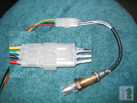
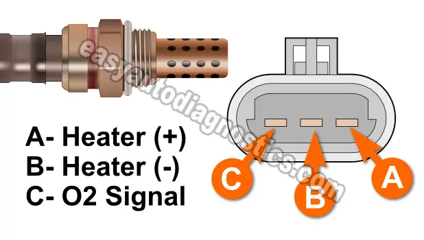
Bosch o2 sensor wiring diagram 3 wire connector. A mass air flow maf sensor responds to the amount of air flowing through a chamber containing the sensor. Sensor connector is shown looking at the mating face. Lay the bosch universal oxygen sensor beside the oe sensor and cut the bosch universal oxygen sensor wiring to the length of the oe sensor. Home car bosch 02 sensor wire diagram car bosch 02 sensor wire diagram.
Universal oxygen o2 sensors it s been more than 40 years since bosch invented the oxygen sensor and began series production in 1976. Bosch 02 sensor wire diagram. Bosch number is 0 258 006 066. This installation electric and wiring diagram alexdapiata.
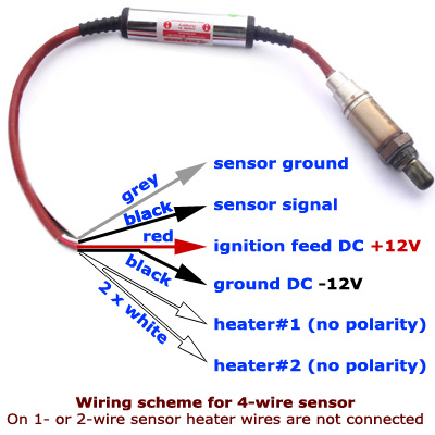
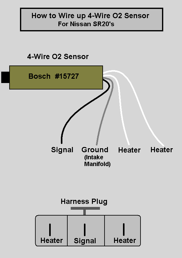
Note that the green pin is from the rcal part inside the sensor connector housing and thus there s no green wire to the sensor assembly represent by the blue area to the right. O2 sensor wiring diagrams duration. Variety of 4 wire oxygen sensor wiring diagram. Removing and reinstalling an o2 sensor connector duration.
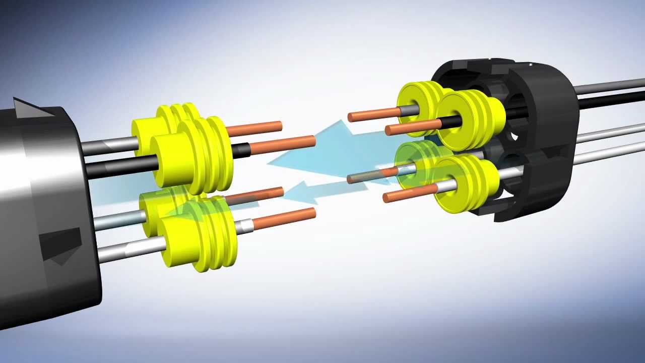
6066 is an lsu 4 0 sensor. Premium oxygen o2 sensors. When you buy universal oxygen sensors you will need to splice the old electrical connector to the new oxygen sensor automd shows you how. Cut the wiring of oe sensor 4 from end of connector as illustrated.
Bosch invented the automotive oxygen sensor which is also referred to as an o2 sensor or lambda sensor. 1 shows the maf sensor made by bosch and fig. Lay the oe sensor beside the bosch universal oxygen sensor and cut the oe sensor wires to the same length as the bosch. The condition of wires between the maf sensor and the onboard controller.
It reveals the components of the circuit as streamlined forms and also the power as well as signal links between the tools. A wiring diagram is a streamlined standard pictorial depiction of an electrical circuit. Bosch o2 sensor with smartlink. Our premium oxygen sensors are thimble and planar switching sensors that are designed to meet or exceed oe specifications.
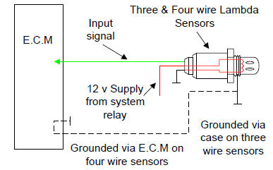
Is not attained check the wiring from terminal 3 to fuse panel using an applicable wiring diagram. Proceed to step 6.

Universal Oxygen O2 Sensors Bosch Auto Parts
Installation Bosch O2 Sensor With Smartlink Youtube
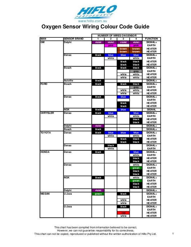
Pdf O2 Sensor Wiring Colour Codes From Http Www Hiflo Com Au
Bosch 4 Wire O2 Sensor

Kr 0107 7 Wire O2 Sensor Wiring Diagram Download Diagram
O2 Sensor Wiring Diagram Internal Lan1 Fuse3 Klictravel Nl

Ew 3385 Universal 4 Wire O2 Sensor Wiring Diagram Wiring Diagram

3 Wire O2 Sensor Wiring Diagram Wiring Diagram
O2 Sensor Problem Mj Tech Modification And Repairs Comanche
Universal O2 Sensor Wiring Diagram Pin Out Lexus Is Forum

Lo 1726 O2 Wiring Diagram
5 Wire O2 Sensor Diagram Testing Bosch Lsu Broadband Oxygen Sensor

Universal Subaru Evo Lambda Sensor Install Bosch Youtube