Receiver Pnp Output Wiring Diagram Emitter M12
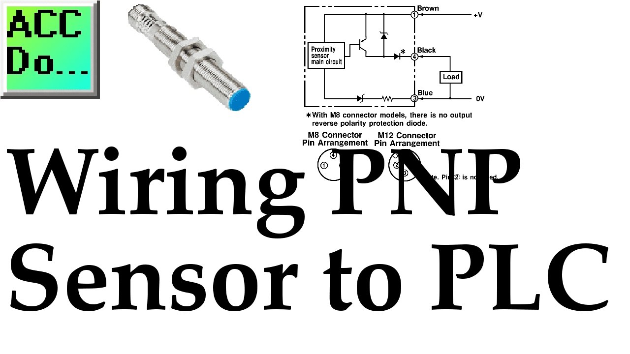
Wiring Pnp Sensor To Plc Youtube

How To Wire A Proximity Sensor To A Plc

1pair Pnp M12 Laser Through Beam Photoelectric Sensor 200ma Cable

Training Series Level I Introduction To Sensors Level I Ppt

Pnp Transistor With Three Led S As A Switch With Images

Go Look Importantbook Type Of Card Transducer Type In Electronics
10 30 vdc pnp switching output changeover wiring diagram functional principle identical to retro reflective sensors emitter and receiver circuitry are incorporated in the.
Receiver pnp output wiring diagram emitter m12. When an ob ject interrupts or weakens the light beam the sensor switches. 40 70 c operating voltage. They are installed opposite each other so that the light from the emitter is aimed directly at the receiver. 10 30 vdc pnp switching output changeover wiring diagram functional principle opposed mode sensors consist of an emitter and receiver.
The default setting of the output is dark operate d o d o. 2 5v or less output operation selectable either light on dark on by type number or by the control input wire. If the application requires the output to turn off when the target is blocking the light between the emitter and receiver the setting may be changed to light operate l o. Setting means that output turns on when the light between the emitter and the receiver is blocked.
Opposed mode sensors are. To order the 3 pin 150 mm 6 inch pigtail with threaded pico style m8 connector models replace the suffix 2m with q3 on the model number. Male m12 1 4 pin protection class ip67 led all round visible operating voltage. Wiring diagrams emitter emitter with beam.
30v dc or less maximum sink current. 30v dc or less maximum sink current. They are installed opposite to each other so that the light from the emitter is aimed directly at the receiver. Pnp open collector transistor applied voltage.
In case of combined load resistive and capacitive the maximum admissible capacity is 0 1 µf for maximum output voltage and current emitter 10 30 vdc 3 bu ov 1 bn 2 wh check pnp receiver 10 30 vdc ov load 100ma 3 bu 1 bn light on. Male m12 1 4 pin protection class ip67 led all round visible sensitivity adjusted via potentiometer operating voltage. Receiver emitters out supply wiring colors 1 bn. The light reflected by the tar get is detected and causes the sensor to switch.
2 5v or less output operation selectable either light on dark on by type number or by the control input wire. 10 30 vdc pnp switching output changeover wiring diagram functional principle emitter and receiver are incorporated in the same housing. M12 1 male connector 4 pin protection classes ip67 ip69k ambient temperature. Receiver npn lo n a s12 2rnrl 2m npn do s12 2aprl 2m pnp lo s12 2rprl 2m pnp do standard 2 m 6 5 ft cable models are listed.

Https Encrypted Tbn0 Gstatic Com Images Q Tbn 3aand9gct7enx8g Eswlxan6nn9ravssdtsnbz9bda 8vpi7gjic3epoa2 Usqp Cau

How To Connect Npn And Pnp Sensors

Photo Eye Sensor How To Wire A Photoelectric Sensor Into A

Transistor Tester Npn Pnp Circuit Jumper Board With Images

Female And Male Sensor Connector Plug 2m Black Line Straight Type

New Original Tlx 12gn02e2 C Taiwan Kai Fang Kfps Twice From
Pdf Datasheet Live

Cx 411 P J World Standard Thru Beam Photoelectric Sensors

Inductive Sensors Compact Fast Reliable Edition Pdf Free Download

Pi2799 Combined Pressure Sensor Eclass 27201302 27 20 13 02

S51 Basic Line Series Pdf Datasensor

Wiring Npn Pnp Brainboxes Industrial Ethernet Io And Serial

Am Pm Series Sensori Induttivi Serie Am E Pm Am Pm Series
